
What must the camera inspect?
Describe the process decision: presence, count, dimension, position, code, text, colour, classification or a visual defect. Also define the result required by the PLC.
Engineering selection guide
Start with the smallest feature production needs to evaluate. Field of view, working distance, motion, lighting and inspection time then determine which MV-SC series and model are technically appropriate.
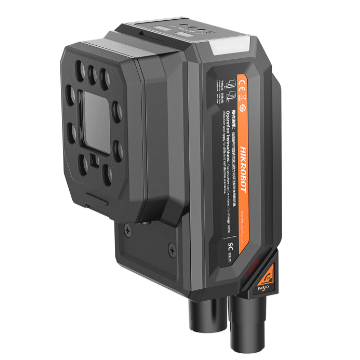
Production problem
Insufficient resolution can hide the relevant feature. A field of view that is too small causes operator intervention when product position varies. Unsuitable lighting creates unstable contrast, while inadequate processing time can lead to missed triggers or a lower line speed.
First define which deviation causes rejection, across which production variation it must remain visible and how much time is available between the trigger and PLC result. The camera follows from those requirements.
Ten selection questions
Describe the process decision: presence, count, dimension, position, code, text, colour, classification or a visual defect. Also define the result required by the PLC.
Measure the width and height that must be visible in one image. Include product tolerance, positioning error and margin for the search area.
Use the smallest defect, character height, code module or measurement edge that must be evaluated reliably. Determine the required pixels per feature with real products.
Measure from the front of the optics to the product and record product-height variation. Working distance and field of view together determine focal length and mounting clearance.
Define line speed, trigger frequency, stationary time and maximum decision time. Test exposure and processing with the heaviest production pattern.
Choose colour only when colour difference is part of the decision. Mono uses every pixel for intensity information and is often preferable for edges, codes and measurement.
Integrated light reduces wiring and installation space. External lighting provides more freedom in direction, surface coverage and size for gloss, relief or a large field of view.
Map the task to specific tools: measurement, pattern matching, OCR, code reading, logic or deep learning. Verify these for each SKU and software version.
Record protocol, digital I/O, trigger method, result format, recipe change and fault handling. Supported protocols vary by series and model.
Use the comparison below to select a series. Then choose resolution, sensor, lens and lighting at SKU level.
Resolution
Use per direction: pixels on feature = camera resolution x feature size / field of view. Rearrange the formula for a first minimum camera resolution. The required number of pixels on the feature is not a fixed catalogue value; establish it using boundary samples, motion and actual lighting.
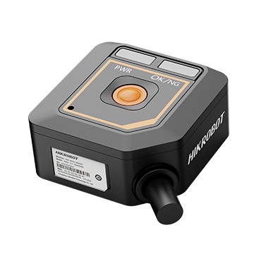
Practical example
The SC1000 fits presence, counting and simple measurement where installation space is limited. The series combines fixed compact optics with white lighting and models for a 120 or 240 mm working distance.
Series overview
The table describes the current product families at a high level. Available functions, frame rate, lighting and connections must be confirmed for the selected SKU.
| Decision point | SC1000 | SC2000 | SC3000 | SC5000 | SC6000 |
|---|---|---|---|---|---|
| Position | Compact vision sensor for defined basic checks. | Faster vision sensor with more recognition tools. | Broad sensor range with rule-based and deep-learning tools. | Vision Master platform for more complex inspection and model choice. | Vision Master platform for high resolution and extended interfaces. |
| Measurement | Basic dimensions, contrast, edges and diameter. | More point, line, edge and pattern measurements. | Extended measurement, calibration and alignment. | Vision Master function modules; confirm the required module per application. | Vision Master function modules for a larger processing workload. |
| OCR | Not found in the family tool specification. | OCR is included in available toolsets. | OCR and learning-based OCR in available toolsets. | Available through Vision Master; verify licence and model. | Available through Vision Master; verify licence and model. |
| AI | No deep-learning module found. | Anomaly and learning-based tools on selected models. | Deep-learning classification and object detection. | Vision Master including a deep-learning module. | Vision Master including a deep-learning module. |
| Resolution | 0.3 to 0.8 MP. | Approximately 0.4 to 2.5 MP, depending on model. | Approximately 1.3 to 6 MP, depending on model. | Approximately 2 to 12 MP. | 1.6 to 25 MP. |
| Optics | Fixed compact optics, 120 or 240 mm working distance. | M10/M12 optics with manual focus and several focal lengths. | M12 optics with focal lengths of approximately 6 to 16 mm. | M12, D14 liquid lens or C-mount. | M12 or C-mount. |
| Typical application | Presence, counting or simple measurement in limited space. | Fast presence, pattern, code or OCR at a compact station. | Measurement, OCR or classification with more resolution and tool capacity. | More complex inspections using Vision Master, AI or interchangeable optics. | Fine detail, large images or applications requiring extra local interfaces. |
Implementation
When several inspections share data or processing capacity, also compare the smart camera with a PC-based vision architecture.
Acceptance test
Business case
Payback can only be calculated using production data. Compare the investment with manual inspection time, rejects and rework, line downtime, changeover time, maintenance and the number of operator interventions.
Checks per shift x handling time x fully loaded labour rate.
Rejects, rework, complaints and wasted material by defect type.
Downtime, reduced line speed and changeover time caused by inspection or faults.
Camera, optics, lighting, mounting, engineering, PLC integration, validation and maintenance.
Next step
Include product images, boundary samples and available installation dimensions. These inputs support a shortlist of series and SKUs that can be compared in a practical trial.