
Detection or measurement
Define which features must be visible and the applicable tolerance, code quality or defect threshold.
Machine vision for production
Product variation, short cycle times and manual checks determine which imaging and automation approach is feasible. Start with the production problem below. The camera, lens, lighting, software and machine interface follow from that requirement.

Choose by production problem
Start with the task that is currently manual, unstable or not traceable. The specialist pages explain the technical boundaries and implementation for each application.

Inspect
Check presence, assembly, print, surfaces or visible defects and send a result to the PLC or line control.
Select by defect definition, contrast, variation and cycle time.

Identify
Read 1D and 2D codes, DPM marks or text and associate the result with a product, order, PLC, MES or database.
Select by code quality, material, speed and no-read handling.

Measure and locate
Determine dimensions, position, height, shape or volume for process control, sorting or control of a subsequent operation.
Choose 2D or 3D based on tolerance, surface and height variation.
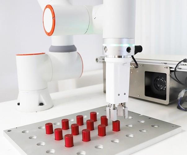
Guide a robot
Locate parts for picking, placing, machine loading or processing and transfer coordinates to the robot in a controlled way.
Choose 2D or 3D based on presentation, height and orientation.

Classify variation
Use a trained model when relevant product or defect variation cannot practically be described with fixed image-processing rules.
Select by dataset, error cost, ownership and behaviour under new variation.

Pick parts from a bin
Plan a reachable, collision-checked pick for parts lying loose in a bin and partially blocking one another from view.
Select by part geometry, visibility, gripper and robot reach.
Technical architecture
The same inspection task can be implemented in several ways. Camera count, product motion, data storage, recipe management, robot integration and maintenance determine the suitable architecture.
Camera and image processing are combined in one industrial housing. This suits defined tasks with local I/O and manageable configuration.
Boundary: processing capacity, multiple cameras, data storage and custom logic.
An industrial PC processes one or more camera streams and provides scope for more extensive software, AI, logging and machine interfaces.
Boundary: broader integration scope, PC management and responsibility for software maintenance.
2D uses contrast in a flat image. 3D adds height or depth for shape, volume, overlapping parts or variable product height.
Choose 3D when the decision genuinely requires depth information.
Fixed rules suit features that can be described consistently by contrast, geometry or dimensions. AI helps with relevant variation that cannot practically be captured in such rules.
AI requires representative data, version control and monitoring of new variation.
From requirement to production
The camera is one component. Reliable operation requires a coordinated choice of field of view, lens, lighting, trigger, processing, mechanical installation and machine communication.
Step 1
Describe good, bad and borderline cases and define the action following each result.
Step 2
Compare camera, lens and lighting using representative products, motion and ambient light.
Step 3
Define processing, I/O, PLC or robot integration, recipe management, logging and error handling.
Step 4
Test timing, product variation, changeovers and fault behaviour under agreed production conditions.
Step 5
Document settings, spares, cleaning, training and responsibilities for changes.
Production acceptance
A demonstration using one good product is insufficient. Define the product variation, speed, error types and fault conditions that the acceptance test must cover.
Define which features must be visible and the applicable tolerance, code quality or defect threshold.
Include approved variants, colour, surface, position, contamination and relevant borderline cases.
Measure trigger, exposure, processing, communication and mechanical action at the highest agreed line load.
Test no-read, uncertain result, timeout, connection loss and reject or robot behaviour.
Check recipe changes, restart, calibration and recovery after downtime without uncontrolled production.
Define who may change thresholds, models, software versions, spares and maintenance procedures.
Business case
The value depends on the current process, the cost of errors and the actions that can follow a vision result. Use measurements from a representative period and state assumptions separately.
Simple calculation model
Annual process value = avoided manual hours + avoided cost of rejects, rework and claims + contribution from available capacity − additional maintenance, licence and ownership costs. Compare this with engineering, hardware, installation, validation and training.
Next step
Send images, product samples and a short description of cycle time, variation, required decision and machine interface. Sedeco can then determine which questions should be answered first in a feasibility test.