
Field of view and detail
The field width and height, together with the smallest edge, gap or defect, determine the required object resolution.
Object resolution = field of view ÷ sensor pixels
Industrial cameras · 2D imaging
An area scan camera captures a complete two-dimensional field of view in each exposure. It is used for presence checks, dimensional measurement, surface inspection and robot guidance when the relevant area fits within one image. Field of view, smallest detail, movement and cycle time determine the suitable model.

Available camera families
The families differ in housing, sensor range, lens mount and interface. Each family page shows the available variants in resolution, monochrome or colour, shutter and connection.
Information that helps compare models
Field of view, smallest relevant detail, product movement, required frame rate, working distance and available installation space.
63 variants · GigE / USB 3
The broad compact C-mount platform: 0.4 to 20 MP, with mono, color and near-infrared options across the family.

36 variants · GigE / USB 3
Compact C-mount cameras for common inspection, measurement and positioning tasks, with variants up to 6 MP.

41 variants · C-mount
Compact 29 mm cube format for restricted installation space and robot-arm mounting, with GigE and USB 3 variants.

16 variants · 1.3 to 20 MP
A focused compact range with GigE and USB 3. The available shutter types suit different combinations of movement and exposure time.

OEM integration
Board-level cameras with C-mount, M12 or no lens mount for OEM integration where installation size takes priority over an enclosed housing.
View MV-CB →
Camera Link
C-mount platform with variants up to 25 MP, including NIR models, for higher data rates in frame-grabber architectures.
View MV-CH →
5 to 604 MP · multiple interfaces
Large-sensor systems with C, F, M58 or M72 mounts and interfaces including 10GigE, Camera Link, CoaXPress and fibre.
Explore High-res →
LWIR and SWIR
For temperature differences or material contrast outside visible light. The suitable model depends on spectral range, optics, measurement range and cooling.
View MV-CI →
Direct HDMI output
Full HD color camera for direct display without a frame grabber: 1920 × 1080, rolling shutter and C-mount.
View the camera →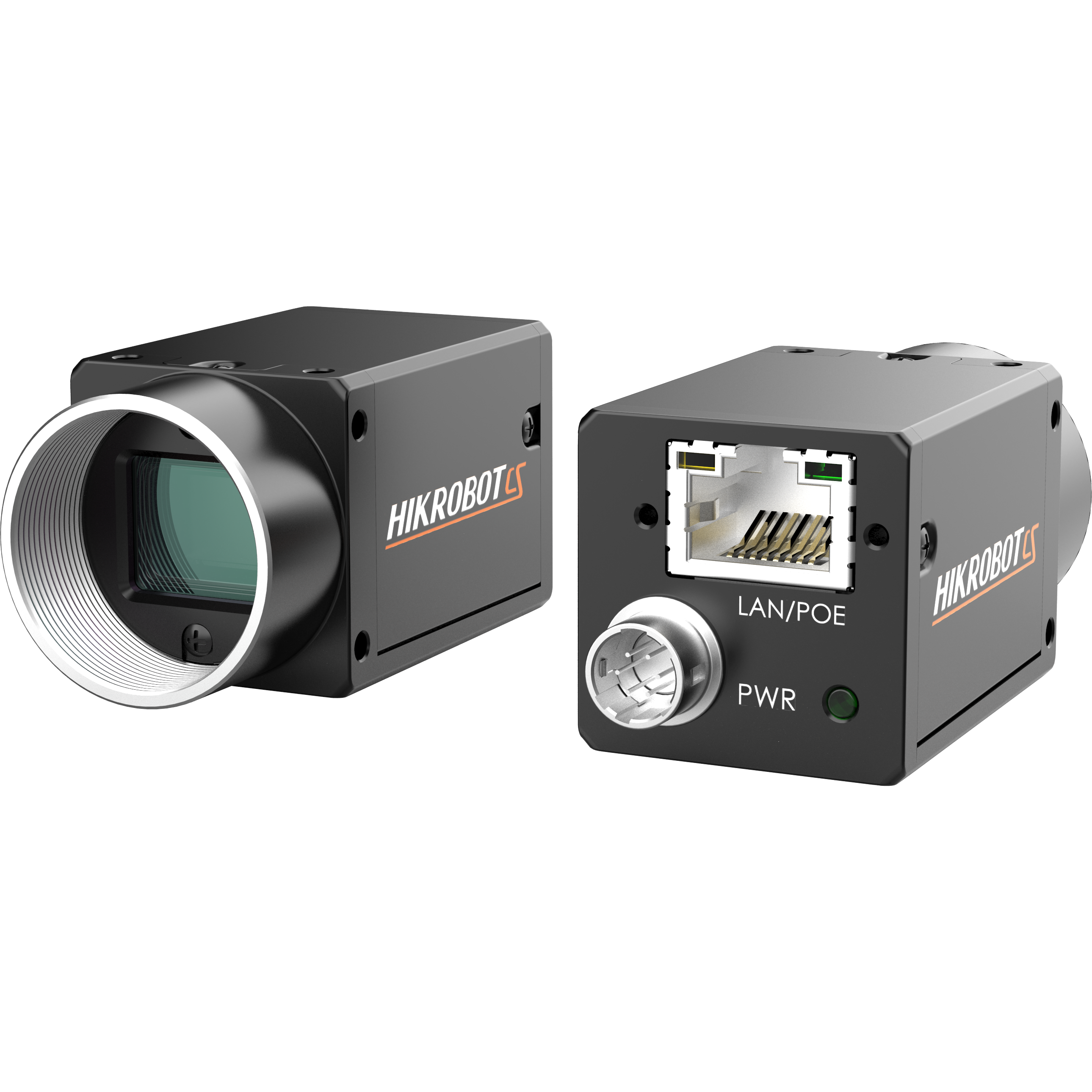
20 MP color · GigE
Sony IMX183, C-mount and rolling shutter for stationary products or applications where controlled strobe timing freezes movement.
View the camera →Specifications that affect the image
The required resolution follows from the field of view and the smallest feature that must remain visible. Movement, interface, lens and lighting then determine whether the camera can deliver that detail at the required speed.
The field width and height, together with the smallest edge, gap or defect, determine the required object resolution.
Object resolution = field of view ÷ sensor pixels
A global shutter avoids the row-to-row timing distortion of a rolling shutter. Exposure must still be short enough to limit motion blur. A rolling-shutter model can suit a stationary scene; pulsed illumination requires a sensor mode and timing that expose all required rows during the pulse.
Blur follows speed × exposure time
Cable length, trigger latency, frame rate and host architecture affect the interface choice. GigE, USB 3, 10GigE, Camera Link and CoaXPress cover different combinations of bandwidth and installation distance.
Data load grows with pixels × bit depth × fps
Sensor format, working distance and aperture affect the lens choice. Lighting geometry and spectrum create the contrast that the camera records.
Assess the complete optical combination
Typical area scan applications
Related camera architectures
Withline scan cameras, the image is built line by line.
Asmart camerasuits a defined inspection with integrated logic and communication.
Theline scan versus area scan guideexplains the difference in acquisition geometry.
Complete imaging setup
A suitable sensor can still produce an unusable image when the lens, lighting, timing or data path does not match the application. Sedeco assesses these components as one connected system.
Technical resources
Sensor geometry, resolution, triggering and the logic behind full-frame acquisition.
How continuous line acquisition differs from capturing a complete two-dimensional field of view.
Compare area scan, line scan, smart cameras and other industrial camera types.
Frequently asked questions
The required pixel resolution follows from the field of view and sensor dimensions. The smallest relevant feature needs enough pixels for the intended algorithm and process tolerance. Additional megapixels are useful only when the optics, lighting, bandwidth and processing can support them.
Global shutter or rolling shutter?A global shutter gives the pixels a common exposure interval, which is useful for moving objects and geometric inspection. It does not remove blur caused by a long exposure. For a rolling shutter, check row timing and permitted distortion. Do not assume a short strobe pulse illuminates every row: confirm the supported exposure mode and synchronisation.
GigE or USB 3?GigE supports longer cable routes and network-based multi-camera layouts; some configurations also support power over the data cable. USB 3 suits short, high-bandwidth connections to a nearby host. Required frame rate, cable length, topology and trigger behaviour decide the fit.
Mono or color?Colour is useful when hue contains inspection information. Monochrome cameras avoid the colour filter array and often provide a clearer image for edge measurement, shape inspection and work in low light.
When is line scan the better choice?Line scan is suited to continuous webs, sheets, cylinders or products whose inspection length is not bounded in the travel direction. Area scan is the natural starting point when the complete relevant surface fits inside a single frame.
Which information helps with camera selection?Useful information for a first camera comparison includes representative products or images, field-of-view dimensions, the smallest relevant feature or defect, object speed, cycle rate, working distance, available space and integration constraints.

Questions about the available models?
Product, field of view, smallest relevant feature, speed, working distance and installation space determine which sensor, shutter, lens, lighting and interface fit. Sedeco can compare the options and test the imaging setup where needed.