
Many cameras
A shared PC can process images from multiple GigE cameras. At higher camera counts, this can reduce hardware cost per camera.
PC-based vision
When a machine must evaluate several images at the same time or in close sequence, central image processing keeps each inspection from becoming a separate system. An industrial PC processes the images from every machine vision camera, manages recipes and sends results to the PLC, robot or MES.

Production problem
A PC-based system becomes relevant when cameras share data or timing. Examples include several views of one part, consecutive checks along a line or different inspections that must finish within the same cycle.
The PC distributes processing capacity across the tasks. Images, recipes, logs and software versions reside in one place. This reduces manual changes at individual cameras and makes maintenance easier to organise. Network load, fault handling and software ownership do become part of the machine design.
A shared PC can process images from multiple GigE cameras. At higher camera counts, this can reduce hardware cost per camera.
Results from different positions or process steps can be combined in one decision flow.
One software release, recipe structure and logging model reduces work during changes and fault analysis.
Technical decision
A smart camera processes its image at the camera. A GigE camera sends the image over Ethernet to the PC. Both can offer interchangeable lenses and high resolutions; the main distinction is how processing, management and interfaces are distributed.
| Decision point | Smart camera | GigE + industrial PC |
|---|---|---|
| Processing | Local to each camera | Central and shared across tasks |
| Management | Configuration and version per camera | Software, recipes and logging on one system |
| Camera count | Practical for independent inspection points | Often more economical when cameras share one process |
| Camera and optics | Selection depends on the smart-camera platform | Broad choice of resolution, sensor size, speed and lens mount |
| Failure scope | A fault usually remains at one inspection point | PC or network faults can affect several inspections; design recovery and redundancy |
| Software | Faster to configure for a standard task | More freedom, with additional development, testing and maintenance |
Components and alternative

Vision controller
An industrial PC for central vision processing. The enclosure limits dust ingress and cooling removes heat. Depending on its size and configuration, it can be installed in the control cabinet. Variants provide multiple GigE ports including PoE, extensive digital I/O and integrated 24 V lighting channels.
View the MV-VC5000 series →
Image acquisition
GigE Vision uses standard Ethernet for image transport. This provides a choice of resolution, frame rate, sensor size and optics. Cable length, bandwidth, triggers and PoE power must be calculated for each installation.
View GigE cameras →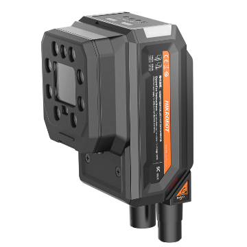
Standalone alternative
For a defined inspection with limited dependencies, processing in the camera is often simpler. Installation, fault isolation and replacement then remain local to the inspection point.
Compare smart cameras →Implementation
Camera count alone does not determine PC capacity. Resolution, frame rate, concurrency, algorithms and retention time together determine network, memory and processor load.
Acceptance test
Business case
Compare more than camera and PC prices. Apply the same production requirements to both architectures and enter the actual project data.
Cameras, lenses, lighting, PC, switches, I/O, cabling and licences.
Configuration, software development, validation, documentation and machine interfaces.
Cycle time, operator interventions, changeover time, rejects, downtime and fault-analysis time.
Software maintenance, spare parts, updates, training and additional inspections.
Next step
Share the camera count, resolution, frames per second, inspection timing, algorithms and required retention time. Jeroen will use these inputs to compare a smart-camera setup with a PC-based system and discuss which approach fits the machine and maintenance team.
Plan a discussion with Jeroen
Jeroen van den Berg
Machine vision engineer