
Application · Pick and place
Pick and place with 2D or 3D vision
For pick and place, the combination of infeed, gripper, destination and cycle time determines how many dimensions are required. Start with the working plane and move up only when height or orientation genuinely changes the motion.
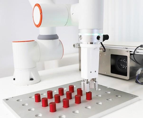
Start with the complete pick-and-place motion
A pick-and-place cycle involves more than finding a part. The robot must approach, pick, withdraw safely, transfer and place within the required tolerance. The vision approach therefore follows from the position and orientation needed for that complete motion.
First define five things: permitted infeed variation, the working plane, gripper design, placement tolerance and available cycle time. This shows whether a position in one plane is sufficient or whether height and tilt must also be measured.
When 2D is usually sufficient
2D suits parts on a conveyor, flat tray or fixture with a known height. The camera determines horizontal position and rotation. The robot uses a fixed approach height and a predefined gripper orientation.
A 2D solution remains simple only when its assumptions remain stable. Verify:
- That part and background remain distinguishable under all production conditions.
- That height variation stays within the depth of field, gripper tolerance and safe approach path.
- That parts do not overlap enough to make contours or features unreliable.
- That the conveyor stops during capture or motion is demonstrably compensated.
- That the destination is reached accurately through the same calibration chain.
When 3D adds value
3D is useful when grasp height varies, parts tilt, the infeed contains multiple levels or spatial orientation is required. The depth measurement must provide more than an attractive point cloud: it must return a pose with demonstrated confidence across the complete working volume.
For randomly piled parts, pose estimation alone is not enough. Visibility, grasp candidates, reachability, collision clearance and recovery must also be designed. This is the boundary between 3D robot guidance and a complete 3D bin-picking solution.
Working plane and calibration
In 2D, calibration defines the relation between image pixels, the working plane and robot coordinates. An error in plane height can still create a horizontal position error, especially with an angled camera. Test the centre and edges of the working area.
In 3D, camera, robot base, tooling and any moving conveyor must share a repeatable coordinate chain. Define who checks calibration, how drift is detected and what happens after maintenance or a collision. Accurate measurement without manageable calibration does not produce a reliable cell.
Control and exception handling
Define communication before vision software and robot code are built separately. The vision result should include at least a pose, quality status and unique cycle identifier. Control logic must distinguish no part found, uncertain measurement, part outside reach, failed pick and unavailable destination.
Each state needs a controlled response: capture again, choose another part, move the infeed, reject the part or request assistance. This prevents a measurement problem from becoming an unexpected robot move or extended line stop.
Calculate time per correct placement
Do not compare 2D and 3D by capture time alone. Measure total production time per correctly picked and placed part. Include detection, depth measurement where applicable, robot motion, pick confirmation, rejects and recovery.
Effective capacity per hour = 3,600 x measured availability / time per correct placement
Use the same part mix and fault definitions in both trials. Fast 2D detection may lose capacity through unstable height; accurate 3D may be too slow or require more support. The complete cycle decides.
Production example: conveyor to fixture
Consider parts arriving flat on a conveyor and being placed into a fixture with a vacuum gripper. If all relevant grasp surfaces are at the same height, 2D can provide position and rotation. A conveyor sensor and timestamp connect the measurement to the moving position.
If the same parts sometimes arrive tilted, grasp height and approach angle also change. A 3D trial must demonstrate that surface and geometry remain measurable in the worst permitted pose. If parts also lie on top of one another and block one another from view, the problem moves into bulk picking with grasp and collision planning.
Business case and acceptance
Compare manual hours per shift, ergonomic load, required output, changeover and intervention costs with camera, robot, gripper, engineering, safeguarding, maintenance and training. Do not use generic savings percentages; populate the model with data from the actual line.
Acceptance should define at least the tested part mix, permitted variation, placement tolerance, how time per correct placement is measured and which failures recover automatically or manually. The broader technology comparison is covered in 2D versus 3D robot vision.
Feasibility
Test infeed, gripper and placement as one system
Share representative parts, extreme presentations, required cycle time and placement tolerance. A trial shows whether 2D is sufficient or which 3D information is required.