
Who it is for
Suitable candidates include machine builders, manufacturers and integrators with a known carrier plane and a visible locating feature. Confirm which team owns calibration, robot motion and changes to the carrier.
Application · 2D robot guidance
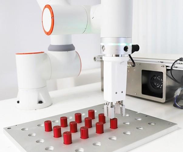
When parts shift within a tray or fixture, a robot may need an updated pickup position for each cycle. A 2D camera can supply X, Y and in-plane rotation when the reference plane and height variation are controlled. Sedeco assesses the image, calibration and controller interface for that defined task.
Problem
Start with the error the gripper can tolerate, the permitted part height and tilt, and whether the part moves after capture. These conditions determine whether a planar calibration remains valid. Compare 2D with height control or 3D measurement when the required contact point cannot be established from the image.
Suitable candidates include machine builders, manufacturers and integrators with a known carrier plane and a visible locating feature. Confirm which team owns calibration, robot motion and changes to the carrier.
Typical tasks include pickup from a stationary tray, correcting placement in a fixture and confirming presence before a grip. On a moving conveyor, the robot also needs validated position tracking between image capture and contact.
Unknown height, tilt, overlap or hidden grip features can invalidate a single-plane result. A 3D method is one option; mechanical presentation control may be another. Test the actual variation before selecting either approach.
Approach
First prove that the locating feature remains visible under product and lighting variation. Calibrate the image to the intended robot plane and document units, axes, angle sign and coordinate frame. Validate at independent positions across the working area; do not reuse only calibration points as acceptance evidence.
Use supported locating tools on a smart camera or external processor. A matching score must be accompanied by a valid-result rule, expected orientation range and a defined outcome for multiple or missing detections.
The detected reference point is not automatically the gripper contact point. Apply the part-relative grip offset and the calibrated tool transform. Send coordinates with validity and cycle identity, and define a timeout that cannot reuse an old position.
Agree whether Sedeco supplies components and configuration advice or implements a defined vision task. The delivery record should identify calibration files, software versions, test results and who validates approach, clearance and robot motion.
Test the centre and edges of the working area, all allowed orientations and the minimum and maximum part heights. Measure contact-position error against an independent reference and compare it with the grip tolerance. Include a missing part, ambiguous detection, communication loss and restart. Confirm that an invalid result cannot start a pick and that restored calibration reproduces the accepted result.

Send the carrier drawing, product samples, permitted height and tilt, grip tolerance, cycle time and robot interface. Estimate camera, optics, lighting and mounting separately from calibration, robot integration and validation hours × rate. Compare these with measured manual loading and recovery work; include recalibration and replacement in maintenance costs.